- Home
- Placa Bus GE Fanuc Serie UR 12A0-0102-A1


Oferta
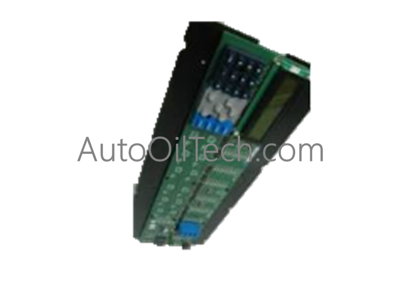
Placa Bus GE Fanuc Serie UR 12A0-0102-A1
No reviews
In stock!
- Part Number: 12A0-0102-A1
- Brand: General Electric
- Type: Placas de autobús de relés
- Dimensions: 4,1 x 12,5 x 10,5 cm
- Country of Origin: EE.UU
- Barcode: 8537101190
Compartir
Additional Specifications
| Color / Pattern |
|
| Power Source |
|
| Communication Protocols |
|
| Controller Design |
|
Tags:
GE Fanuc UR
,
Relay Bus Boards
Descripción del Producto
Configurada para la transferencia de datos de alta velocidad y la comunicación de bus interno en las redes de la serie GE Universal Relay (UR), la GE Fanuc 12A0-0102-A1 (Tarjeta de Bus de la serie UR 12A0-0102-A1) proporciona una ejecución física/eléctrica directa.
Desglose del sufijo y matriz del modelo
| Sufijo del modelo | Arquitectura de función principal | Aplicación arquitectónica |
|---|---|---|
| 12A0-0102-A1 | Tarjeta de bus de backplane interno estándar | Serie GE Universal Relay (UR) |
| 12A0-0102-... | Familia de variantes base | Marcos de relé de protección Multilin |
Especificaciones del hardware
| Parámetro | Especificación |
|---|---|
| Modelo | 12A0-0102-A1 |
| Marca | GE Fanuc |
| Origen | EE. UU. |
| Peso | 0,65 kg |
| Dimensiones | 250,0 mm x 120,0 mm x 20,0 mm |
| Temperatura de funcionamiento | -40 °C a +70 °C |
| Consumo de energía | 5,0 W nominal |
| Tensión de funcionamiento | 24 VCC |
| Interfaz de comunicación | Bus de backplane interno de alta velocidad |
| Compatibilidad del sistema | Serie GE UR, modelos UR200 |
Redes deterministas Profinet/EtherNet/IP y compatibilidad con firmware Flash
La tarjeta de bus 12A0-0102-A1 utiliza una arquitectura robusta de velocidad de comunicación de bus de backplane para gestionar las tasas de intercambio de datos entre los subsistemas de relé UR modulares. Mantiene una distribución de señal de baja latencia entre los módulos de procesamiento enchufables y las unidades de potencia, al mismo tiempo que soporta interferencias electromagnéticas industriales severas. Además, la compatibilidad con el firmware flash interno garantiza que la lógica del controlador de bus integrado se pueda actualizar a través de herramientas de gestión autorizadas sin necesidad de reemplazar el hardware.
Preguntas frecuentes
P: ¿Cuál es la función principal de la tarjeta 12A0-0102-A1 dentro de la arquitectura de relé UR?
R: Sirve como tarjeta de bus de backplane interno, proporcionando comunicación de datos de alta velocidad y enlaces de distribución de energía entre los diversos módulos enchufables del sistema GE Universal Relay.
P: ¿Qué tensión nominal requiere la tarjeta de bus para el funcionamiento interno del sistema?
R: La tarjeta funciona con una entrada de alimentación de CC regulada de 24 VCC suministrada por el módulo de alimentación principal del chasis del relé.
Pautas de instalación en campo
Asegúrese de que todas las fuentes de alimentación de CA y CC externas al chasis del relé UR estén completamente desconectadas antes de instalar o reemplazar la tarjeta de bus 12A0-0102-A1. Manipule la placa de circuito impreso por los bordes mientras usa una muñequera ESD para evitar daños por descarga electrostática a los componentes sensibles. Deslice la tarjeta de forma segura en sus ranuras de montaje del backplane designadas, asegurándose de que todos los conectores de borde estén completamente asentados antes de apretar los tornillos de fijación.
Have a question?