- Home
- Relé de gestión de alimentadores serie GE 750 GE 750-P5-G5-S5-HI-A20-G-E


Oferta
Relé de gestión de alimentadores serie GE 750 GE 750-P5-G5-S5-HI-A20-G-E
No reviews
In stock!
- Part Number: 750-P5-G5-S5-HI-A20-G-E
- Brand: GE Fanuc
- Type: Relé de Gestión de Alimentadores
- Dimensions: 2,1 x 18,6 x 26,3 cm
- Country of Origin: EE.UU
- Barcode: 8537101190
Compartir
Additional Specifications
| Color / Pattern |
|
Descripción del Producto
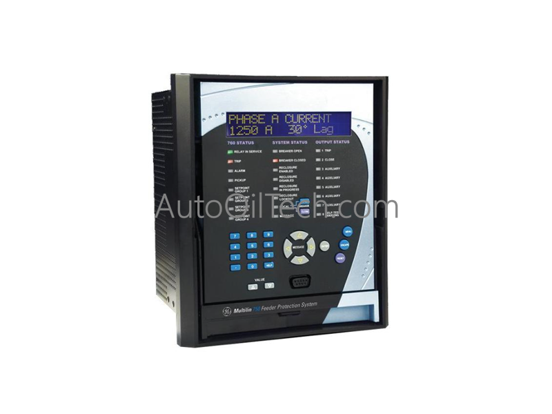
El GE Multilin 750-P5-G5-S5-HI-A20-G-E, también catalogado como el Relé de Gestión de Alimentadores 750, funciona como un componente de hardware dedicado para la protección, control y monitoreo de alimentadores de distribución de energía de tamaño mediano a grande dentro de redes eléctricas industriales. Este conjunto de hardware extraíble combina la detección de fallas, el control de interruptores, la medición de potencia y el registro de eventos de alta resolución en una única plataforma de procesamiento.
Especificaciones de hardware
| Parámetro | Especificación |
|---|---|
| Modelo | 750-P5-G5-S5-HI-A20-G-E |
| Marca | GE Multilin (General Electric) |
| Serie | Serie de Gestión de Alimentadores GE Multilin 750 |
| Origen | Canadá |
| Peso | 6,35 kg (14 lbs) |
| Dimensiones | 252 x 216 x 224 mm |
| Temperatura de funcionamiento | -40 a +70 °C |
| Consumo de energía | Regulado a través de una arquitectura de potencia interna de alto rango (HI) |
| Salidas analógicas | Ocho (8) bucles de corriente activa de 4 a 20 mA |
| Sincronización horaria | Canal de entrada IRIG-B para una coordinación precisa de reloj externo |
| Estilo de la carcasa | Configuración de caja extraíble totalmente modular |
| Elementos de protección | Sobrecorriente, falla a tierra, falla de interruptor, sobrecarga térmica, voltaje, frecuencia |
| Diagnóstico de eventos | Secuencia de Eventos (SOE), captura de forma de onda, registro continuo de datos |
| Integración de software | Utilidad EnerVista 750 para configuración de puntos de ajuste y análisis de tendencias |
Velocidad de comunicación del bus de la placa base y arquitectura de firmware
El conjunto de gestión de alimentadores utiliza unidades de procesamiento de alta densidad para mantener una velocidad de comunicación de datos óptima a través del bus interno de la placa base. Al aplicar parámetros estrictos de compatibilidad de flash de firmware en los registros de hardware activos, el núcleo de procesamiento puede calcular simultáneamente métricas de potencia, escanear entradas multicanal y evaluar ecuaciones de fallas. Las corrientes y voltajes analógicos brutos de transformadores externos se digitalizan instantáneamente, enrutándose a través de canales de bus internos al procesador lógico. Esta ruta ejecuta la lógica de sobrecorriente protectora y de falla a tierra en ventanas de milisegundos, dirigiendo las señales de disparo a los circuitos de control del interruptor y publicando datos de telemetría a través de enlaces Modbus, DNP3 o SCADA en red sin demoras en el almacenamiento en búfer de datos.
Preguntas frecuentes
P: ¿Cómo evita el diseño físico de la carcasa extraíble las interrupciones operativas durante el mantenimiento del relé?
R: El chasis extraíble está diseñado con barras de cortocircuito mecánicas automáticas en los bloques de terminales de la placa base. Cuando un operador extrae la unidad de relé interna para mantenimiento o prueba, estos mecanismos de cortocircuito se cierran automáticamente, conectando en puente los secundarios del transformador de corriente primario antes de que puedan alcanzar un estado peligroso de circuito abierto.
P: ¿Qué funcionalidad proporciona la entrada de hardware IRIG-B integrada?
R: La conexión IRIG-B acepta una señal de sincronización horaria externa estandarizada de un sistema de reloj maestro. Esta señal sincroniza el núcleo del reloj interno con una resolución de milisegundos, lo que permite que el registrador de secuencia de eventos (SOE) y las capturas de forma de onda se puedan referenciar con precisión con otros relés en una red de distribución de energía de área amplia.
Have a question?