- بيت
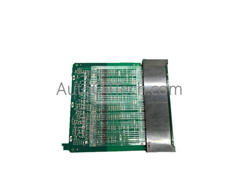
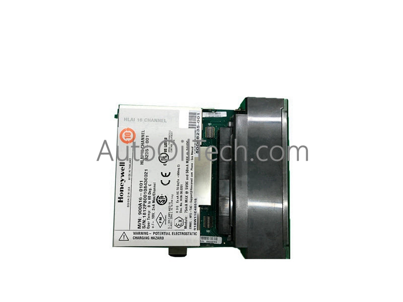
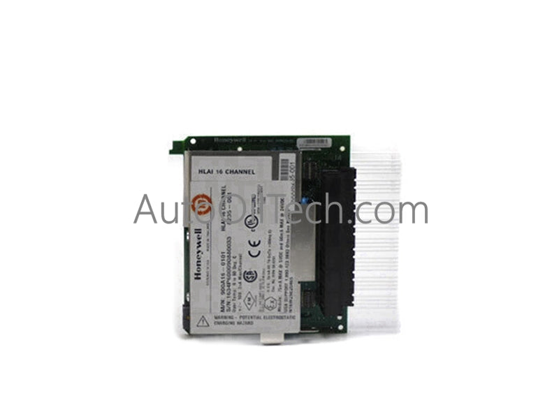
- وحدة الإدخال/الإخراج Honeywell 900K01-0201
أُوكَازيُون


أُوكَازيُون
وحدة الإدخال/الإخراج Honeywell 900K01-0201
No reviews
في الأوراق المالية!
- Part Number: 900K01-0201
- Brand: Honeywell
- Type: وحدة الإدخال/الإخراج
- Dimensions: 3.7×14×13.6 سم
- Country of Origin: الولايات المتحدة الأمريكية
- Barcode: 8537101190
يشارك
Additional Specifications
| Color / Pattern |
|
| Power Source |
|
| Communication Protocols |
|
| Controller Design |
|
وصف المنتج
وحدة الإدخال/الإخراج Honeywell 900K01-0201
تم تكوينها لمهام إشارات النبض المختلطة والترددية والرقمية في معماريات HC900/ControlEdge، وتوفر الوحدة Honeywell 900K01-0201 (وحدة الإدخال/الإخراج 900K01-0201) تنفيذًا كهربائيًا مباشرًا لالتقاط الإدخال منخفض الجهد، ومعالجة العداد، وإشارات الإخراج ذات المجمع المفتوح.
مواصفات الجهاز
| المعلمة | المواصفات |
|---|---|
| النموذج | 900K01-0201 |
| العلامة التجارية | Honeywell |
| المنشأ | غير محدد |
| الوزن | 360 جرام |
| الأبعاد | 137 مم ارتفاع × 35.6 مم عرض (5.4 بوصة × 1.4 بوصة) |
| درجة حرارة التشغيل | غير محددة |
| استهلاك الطاقة | غير محدد |
| نطاق جهد الإدخال | 0 فولت تيار مستمر إلى 24 فولت تيار مستمر |
| الإدخالات الرقمية لكل وحدة | 4 |
| نوع الإخراج الرقمي | جامع مفتوح، 5-24 فولت، 30 مللي أمبير كحد أقصى |
| نطاق جهد إدخال النبض | 0-24 فولت تيار مستمر |
| مستوى تشغيل النبض | 3.0 فولت تيار مستمر كحد أدنى |
| مستوى إيقاف النبض | 1.0 فولت تيار مستمر كحد أقصى |
| مقاومة إدخال النبض | 25 كيلو أوم |
| نطاق تردد النبض | 0-10 كيلو هرتز |
| الحد الأدنى لعرض النبض | 3 ميكرو ثانية |
| حجم العداد | 32 بت |
| نطاق إدخال التردد | 10 هرتز إلى 100 كيلو هرتز |
| الحد الأدنى لعرض نبضة إدخال التردد | 500 ميكرو ثانية (10-500 هرتز)، 50 ميكرو ثانية (10-5 كيلو هرتز)، 2.5 ميكرو ثانية (10-100 كيلو هرتز) |
| نطاق تردد إخراج النبض | 25 هرتز إلى 10 كيلو هرتز |
| دورة عمل إخراج النبض | 50% ثابتة |
| مدة إخراج النبض | نبضات مستمرة أو مرقمة |
بروتوكول حلقة HART بـ 4-20 مللي أمبير واعتبارات شبكة الفيلدبص (Fieldbus)
على الرغم من أن الوحدة 900K01-0201 هي وحدة إدخال/إخراج منفصلة/نبضية، إلا أن سلوكها يتفاعل مع شبكات التحكم في العمليات من Honeywell حيث تتواجد إشارات تناظرية ورقمية مختلطة. تضمن عتبات الإدخال الثابتة للتيار المستمر عدم تفسير ترددات HART المتراكبة على الأسلاك القريبة بشكل خاطئ على أنها حواف نبضية. عند النشر في بيئات FOUNDATION Fieldbus أو Profibus PA، يمنع العزل من قناة إلى قناة داخل منصة HC900/ControlEdge نشاط النبض الرقمي من الاقتران بالوحدات التناظرية المجاورة. تحافظ دوائر تعويض الوصلات الباردة (CJC) في وحدات درجة الحرارة على دقة المرجع عند مراعاة فصل الأسلاك وممارسات التأريض.
الأسئلة المتكررة
س: هل يمكن استخدام قناة في وقت واحد لإدخال النبض والتردد؟ ج: لا. يؤدي تخصيص قناة لإخراج النبض إلى جعل تلك القناة غير متاحة لوظائف إدخال النبض أو التردد.
س: هل تدعم الوحدة التبديل السريع (Hot-swap)؟ ج: لم يتم تصميم الوحدة للتبديل السريع. يجب إزالة طاقة اللوحة الخلفية قبل التثبيت أو الإزالة لتجنب تلف حالة الإشارة.
س: كيف يتم الإشارة إلى تجاوز العداد؟ ج: يتم تعيين علامة تجاوز السعة (OVERFLOW) (STS=33) عندما يتجاوز العداد ذو 32 بت قيمته القصوى. يتم إعادة ضبطها عند انتقال RST من إيقاف إلى تشغيل.
إرشادات التثبيت في الموقع
حافظ على الأسلاك ضمن نطاق الجهد المنخفض المحدد وتأكد من انتقالات الحافة النظيفة لمدخلات النبض والتردد. يجب ربط أسلاك الكابلات المحمية عند نقطة إنهاء واحدة لمنع التيارات الدوارة. قم بتوجيه أسلاك النبض/التردد بشكل منفصل عن الموصلات عالية التيار لتقليل حقن الضوضاء. تتطلب مخرجات المجمع المفتوح مقاومات سحب خارجية بحجم يتناسب مع جهد النظام وتيار الحمل. عند تهيئة الإجراءات المحددة مسبقًا أو إعادة تعيين العدادات، تحقق من أن منطق ControlEdge Builder يمنع ظروف الإغلاق غير المقصودة.
هل لديك سؤال؟