- بيت
- مرحل إدارة وحدة التغذية من السلسلة GE 750 (GE 750-P5-G5-S5-HI-A20-G-E)
أُوكَازيُون


أُوكَازيُون
مرحل إدارة وحدة التغذية من السلسلة GE 750 (GE 750-P5-G5-S5-HI-A20-G-E)
No reviews
في الأوراق المالية!
- Part Number: 750-P5-G5-S5-HI-A20-G-E
- Brand: GE Fanuc
- Type: مرحل إدارة وحدة التغذية
- Dimensions: 2.1 × 18.6 × 26.3 سم
- Country of Origin: الولايات المتحدة الأمريكية
- Barcode: 8537101190
يشارك
Additional Specifications
| Color / Pattern |
|
وصف المنتج
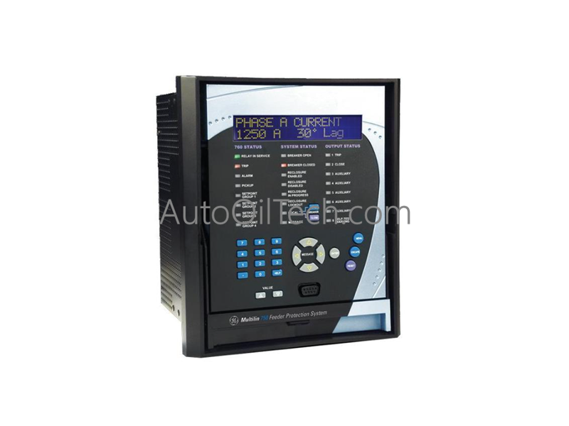
تعمل GE Multilin 750-P5-G5-S5-HI-A20-G-E، والتي تم فهرستها أيضًا باسم مرحل إدارة المغذي 750، كمكون مادي مخصص للحماية والتحكم والمراقبة لمغذيات توزيع الطاقة متوسطة إلى كبيرة الحجم ضمن الشبكات الكهربائية الصناعية. يجمع هذا التجميع المادي القابل للسحب بين اكتشاف الأعطال، والتحكم في القاطع، وقياس الطاقة، وتسجيل الأحداث عالية الدقة في منصة معالجة واحدة.
المواصفات المادية
| المعلمة | المواصفات |
|---|---|
| النموذج | 750-P5-G5-S5-HI-A20-G-E |
| العلامة التجارية | GE Multilin (جنرال إلكتريك) |
| السلسلة | سلسلة GE Multilin 750 لإدارة المغذي |
| المنشأ | كندا |
| الوزن | 14 رطلاً |
| الأبعاد | 252 × 216 × 224 ملم |
| درجة حرارة التشغيل | -40 إلى +70 درجة مئوية |
| استهلاك الطاقة | يتم تنظيمه عبر بنية طاقة داخلية عالية المدى (HI) |
| المخرجات التناظرية | ثمانية (8) حلقات تيار نشطة من 4 إلى 20 مللي أمبير |
| مزامنة الوقت | قناة إدخال IRIG-B لتنسيق ساعة خارجية دقيق |
| نمط الغلاف | تكوين غلاف قابل للسحب بالكامل |
| عناصر الحماية | التيار الزائد، عطل التأريض، عطل القاطع، الحمل الحراري الزائد، الجهد، التردد |
| تشخيصات الأحداث | تسلسل الأحداث (SOE)، التقاط شكل الموجة، تسجيل البيانات المستمر |
| تكامل البرامج | برنامج EnerVista 750 لتكوين نقطة الضبط وتحليل الاتجاهات |
سرعة الاتصال الناقل الخلفي وبنية البرامج الثابتة
يستخدم تجميع إدارة المغذي وحدات معالجة عالية الكثافة للحفاظ على سرعة اتصال البيانات المثلى عبر ناقل اللوحة الخلفية الداخلي. يتيح تطبيق معلمات توافق صارمة للبرامج الثابتة عبر مسجلات الأجهزة النشطة لنواة المعالجة حساب مقاييس الطاقة في وقت واحد، ومسح المدخلات متعددة القنوات، وتقييم معادلات الأعطال. يتم رقمنة التيارات والجهود التناظرية الخام من المحولات الخارجية على الفور، وتوجيهها عبر قنوات الناقل الداخلية إلى معالج المنطق. ينفذ هذا المسار منطق الحماية من التيار الزائد وعطل التأريض في غضون أجزاء من الثانية، ويوجه إشارات الفصل إلى دوائر التحكم في القاطع وينشر بيانات القياس عن بعد عبر Modbus أو DNP3 أو روابط SCADA المتصلة بالشبكة دون تأخير في تخزين البيانات المؤقت.
الأسئلة المتداولة
س: كيف يمنع تصميم الغلاف القابل للسحب المادي حدوث اضطرابات تشغيلية أثناء صيانة المرحل؟
ج: تم تصميم الهيكل القابل للسحب بقضبان تقصير ميكانيكية تلقائية على أطراف اللوحة الخلفية. عندما يقوم المشغل بسحب وحدة المرحل الداخلية للصيانة أو الاختبار، تغلق آليات التقصير هذه تلقائيًا، وتربط ثواني محول التيار الأولي قبل أن تصل إلى حالة دائرة مفتوحة خطيرة.
س: ما هي الوظيفة التي يوفرها إدخال الأجهزة IRIG-B المدمج؟
ج: يقبل اتصال IRIG-B إشارة مزامنة وقت خارجية قياسية من نظام ساعة رئيسي. تقوم هذه الإشارة بمزامنة نواة الساعة الداخلية بدقة مللي ثانية، مما يسمح بالربط المرجعي الدقيق لسجل تسلسل الأحداث (SOE) والتقاطات شكل الموجة مع مرحلات أخرى عبر شبكة توزيع طاقة واسعة النطاق.
هل لديك سؤال؟