- Home
- Yokogawa SARM55 Mechanical Relay Board


Sale
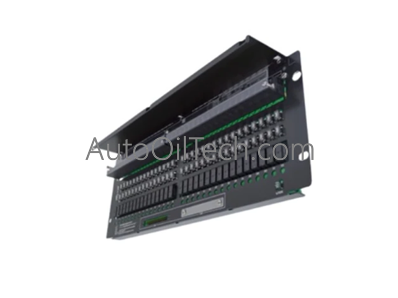
Yokogawa SARM55 Mechanical Relay Board
No reviews
In stock!
- Part Number: SARM55W
- Brand: Yokogawa
- Type: Mechanical Relay Board
- Dimensions: 3.3x10.7x13cm
- Country of Origin: Japan
- Barcode: 8537101190
Share
Additional Specifications
| Color / Pattern |
|
| Power Source |
|
| Communication Protocols |
|
| Controller Design |
|
Product Description
The Yokogawa SARM55, also cataloged as the ARM55C Mechanical Relay Board, operates as a dedicated hardware component for multi-channel discrete output execution within Yokogawa industrial control platforms. The solid-state interface assembly processes binary logic commands to route physical dry contact outputs over external switching circuits.
Hardware Specifications
| Parameter | Specification |
|---|---|
| Model | SARM55 |
| Brand | Yokogawa |
| Origin | Japan |
| Weight | 2.2 kg |
| Dimensions | 482.6 mm x 132.5 mm (Standard 19 inch rack, 3U height profile) |
| Operating Temp | 0 to 50 deg C |
| Power Consumption | 24 VDC internal circuit power, Max. 0.65 A current draw |
| Contact Points | 32 point discrete output matrix |
| Contact Type | Form a (Normally Open) or Form b (Normally Closed) dry contacts |
| Maximum AC Load | 250 VAC at 2 A per point |
| Maximum DC Load | 30 VDC at 2 A | 125 VDC at 0.1 A per point |
| Minimum Loop Load | 5 VDC, 10 mA electrical threshold |
| Insulation Resistance | At least 10 MOhm (Evaluated at 500 VDC) |
| Withstanding Voltage | Field to Case: 2 kV | Power to Case: 500 V | Power to Field: 2 kV |
| Field Terminals | M4 screw connection layout |
| Module Compatibility | ADV551 (with ATD5A block) | ADV561 digital output cards |
| Signal Interconnects | AKB331 (32 point link) | AKB337 (64 point link) cables |
| Regulatory Standards | EMC Standards [CE Marking], [C-Tick Marking], [KC Marking] |
| Product Type | Digital I/O Cards |
Process Control & DCS Instrumentation Rails
- Channel-to-Channel Isolation and Noise Suppression The board infrastructure implements structural galvanic isolation limits rated at 2 kV between the M4 field device terminals and the internal system logic. This barrier prevents high-voltage transient surges, electrical switching noise, and common-mode voltage offsets from bleeding back into adjacent channels or degrading nearby low-level measurement loops.
- 4-20 mA HART Loop Protocol Coexistence By providing clean mechanical dry contacts, the assembly prevents electrical cross-talk within cabinets housing 4-20 mA HART loop protocol lines. The high insulation resistance of 10 MOhm at 500 VDC ensures that switching heavy inductive loads does not introduce harmonic distortions or loop leakage currents into adjacent distributed control system (DCS) analog instrumentation.
Frequently Asked Questions
Q: How does the minimum load requirement impact low-power signaling circuits?
A: The contacts require a minimum loop load of 5 V, 10 mA to function reliably. Attempting to switch electronic signals below this threshold can lead to intermittent continuity over time, as the loop lacks the electrical wetting energy necessary to pierce microscopic surface oxide layers that build up naturally on electromechanical contact surfaces.
Q: What structural behavior occurs if the internal 24 VDC logic power grid fails?
A: The internal logic circuits operate on a nominal 24 VDC rail with a maximum current draw of 0.65 A. If this internal control power supply is interrupted or drops below minimum operational thresholds, the electromagnetic coils de-energize immediately, reverting all 32 channels to their default unpowered safe states to guarantee predictable contact positions.
Have a Question?