- Home
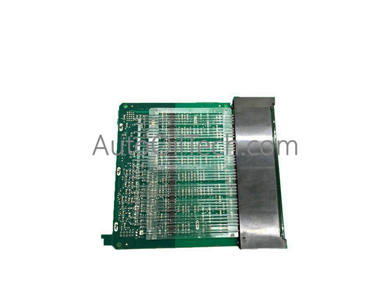
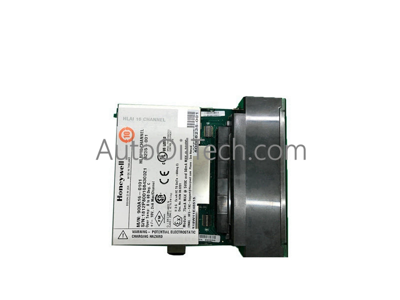
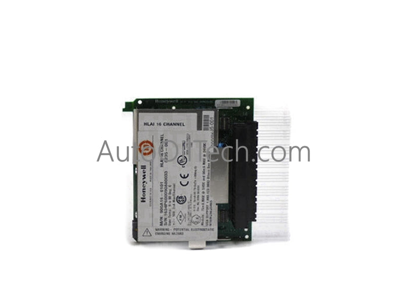
- Honeywell 900K01-0201 Input/Output Module


Sale
Honeywell 900K01-0201 Input/Output Module
No reviews
In stock!
- Part Number: 900K01-0201
- Brand: Honeywell
- Type: Input/Output Module
- Dimensions: 3.7×14×13.6cm
- Country of Origin: USA
- Barcode: 8537101190
Share
Additional Specifications
| Color / Pattern |
|
| Power Source |
|
| Communication Protocols |
|
| Controller Design |
|
Product Description
Honeywell 900K01-0201 Input/Output Module
Configured for mixed pulse, frequency, and digital signaling tasks in HC900/ControlEdge architectures, the Honeywell 900K01-0201 (900K01-0201 I/O module) provides direct electrical execution of low‑voltage input capture, counter processing, and open‑collector output signaling.
Hardware Specifications
| Parameter | Specification |
|---|---|
| Model | 900K01-0201 |
| Brand | Honeywell |
| Origin | Not specified |
| Weight | 360 g |
| Dimensions | 137 mm H × 35.6 mm W (5.4 in × 1.4 in) |
| Operating Temp | Not specified |
| Power Consumption | Not specified |
| Input Voltage Range | 0 VDC to 24 VDC |
| Digital Inputs per Module | 4 |
| Digital Output Type | Open collector, 5–24 V, 30 mA max |
| Pulse Input Voltage Range | 0–24 VDC |
| Pulse ON Level | 3.0 VDC minimum |
| Pulse OFF Level | 1.0 VDC maximum |
| Pulse Input Impedance | 25 kΩ |
| Pulse Frequency Range | 0–10 kHz |
| Minimum Pulse Width | 3 µsec |
| Counter Size | 32‑bit |
| Frequency Input Range | 10 Hz to 100 kHz |
| Frequency Input Minimum Pulse Width | 500 µsec (10–500 Hz), 50 µsec (10–5 kHz), 2.5 µsec (10–100 kHz) |
| Pulse Output Frequency Range | 25 Hz to 10 kHz |
| Pulse Output Duty Cycle | 50% fixed |
| Pulse Output Duration | Continuous or numbered pulses |
4-20 mA HART Loop Protocol and Fieldbus Considerations
Although the 900K01-0201 is a discrete/pulse I/O module, its behavior interacts with Honeywell process‑control networks where mixed analog and digital signaling coexist. Stable DC input thresholds ensure that superimposed HART frequencies on nearby wiring are not misinterpreted as pulse edges. When deployed in FOUNDATION Fieldbus or Profibus PA environments, channel‑to‑channel isolation within the HC900/ControlEdge platform prevents digital pulse activity from coupling into adjacent analog modules. Cold junction compensation (CJC) circuits in temperature modules maintain reference accuracy when wiring separation and grounding practices are observed.
Frequently Asked Questions
Q: Can a channel be used simultaneously for pulse and frequency input? A: No. Assigning a channel for pulse output renders that channel unavailable for pulse or frequency input functions.
Q: Does the module support hot‑swap insertion? A: The module is not designed for hot‑swap. Backplane power should be removed before installation or removal to avoid signal state corruption.
Q: How is counter overflow indicated? A: The OVERFLOW flag (STS=33) is set when the 32‑bit counter exceeds its maximum value. It resets on an OFF‑to‑ON transition of the RST input.
Field Installation Guidelines
Maintain wiring within the specified low‑voltage range and ensure clean edge transitions for pulse and frequency inputs. Shielded cable grounds should be bonded at a single termination point to prevent circulating currents. Route pulse/frequency wiring separately from high‑current conductors to minimize noise injection. Open‑collector outputs require external pull‑up resistors sized according to system voltage and load current. When configuring preset actions or counter resets, verify that ControlEdge Builder logic prevents unintended latch conditions.
Have a Question?