- Home
- Honeywell 51202942-200 Smart Transmitter Interface Module


Sale
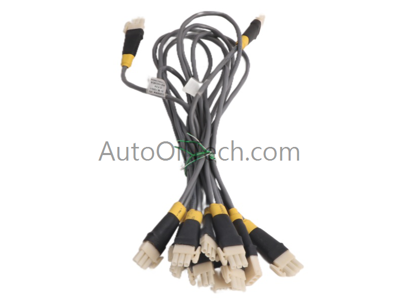
Honeywell 51202942-200 Smart Transmitter Interface Module
No reviews
In stock!
- Part Number: 51202942-200
- Brand: Honeywell
- Type: Smart Transmitter Interface Module
- Dimensions: 7x14x14.5cm
- Country of Origin: USA
- Barcode: 8537101190
Share
Additional Specifications
| Color / Pattern |
|
| Power Source |
|
| Controller Design |
|
Product Description
Honeywell 51202942-200 Smart Transmitter Interface Module
The Honeywell 51202942-200, also cataloged as the 51202942-200 Smart Transmitter Interface Module, operates as a dedicated hardware component for multi‑channel SmartLine transmitter communication within Experion PKS and C300 controller networks. The module executes digitally enhanced transmitter polling, channel acquisition, and field‑device data transfer over extended cable distances.
Hardware Specifications
| Parameter | Specification |
|---|---|
| Model | 51202942-200 |
| Brand | Honeywell |
| Origin | USA |
| Weight | 0.4 kg |
| Dimensions | 70 mm × 25 mm × 125 mm (cabinet listing also shows 7 × 14 × 14.5 cm) |
| Operating Temp | 0 to 55 deg C |
| Power Consumption | 10 W |
| Voltage Range | 10–32 VDC |
| Channels | 8 Smart Transmitter Interface channels |
| Protocol | Honeywell Digitally Enhanced (D.E.) protocol |
| Max Cable Distance | Up to 1000 m (D.E. communication) |
| System Platform | Experion PKS / C300 |
| Module Type | Smart Transmitter Interface Module |
| Communication Service | Ethernet router (system-level listing) |
4-20 mA HART Loop Protocol and Fieldbus Interaction
Honeywell SmartLine and D.E. protocol devices often coexist with 4-20 mA HART loops in mixed DCS environments. The 51202942-200 maintains channel‑to‑channel isolation to prevent HART superimposed frequencies from interfering with D.E. polling cycles. When deployed alongside FOUNDATION Fieldbus or Profibus PA modules, wiring separation ensures that digital polling bursts do not couple into analog temperature modules using cold junction compensation circuits. Stable supply voltage across the 10–32 VDC range preserves transmitter reference accuracy and prevents drift in loop‑powered instruments.
Frequently Asked Questions
Q: Can the 51202942-200 be hot‑swapped in a powered C300 chassis? A: No. The module is not designed for hot‑swap. Backplane power must be removed before insertion or removal.
Q: Does the module support non‑SmartLine transmitters? A: The module is optimized for Honeywell SmartLine 3000 devices using the D.E. protocol. Standard analog transmitters require separate analog input modules.
Q: How does cable length affect D.E. communication? A: D.E. polling remains stable up to 1000 m when proper shielding, grounding, and conductor sizing are maintained.
Field Installation Guidelines
Maintain shield bonding at a single termination point to avoid circulating currents along long transmitter runs. Route D.E. communication wiring separately from high‑current conductors to minimize noise coupling. Ensure terminal engagement is secure and within the recommended conductor size. When integrating with mixed analog and digital modules, preserve isolation boundaries by maintaining proper spacing and grounding between Smart Transmitter Interface channels and analog loops. Avoid running D.E. communication cables parallel to variable‑frequency drive outputs or relay coils.
Have a Question?