- Home
- GE IS200GDDDG1ABA Gate Driver and Dynamic Discharge Board


Sale
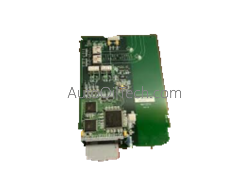
GE IS200GDDDG1ABA Gate Driver and Dynamic Discharge Board
No reviews
In stock!
- Part Number: IS200GDDDG1ABA
- Brand: General Electric
- Type: Gate Driver and Dynamic Discharge Board
- Dimensions: 4x18.5x12.7cm
- Country of Origin: USA
- Barcode: 8537101190
Share
Additional Specifications
| Color / Pattern |
|
| Power Source |
|
| Communication Protocols |
|
| Controller Design |
|
Product Description
GE IS200GDDDG1ABA Gate Driver and Dynamic Discharge Board
Configured for IGBT gate drive isolation and dynamic discharge control in EX2000 exciter networks, the GE IS200GDDDG1ABA (IS200GDDDG1ABA gate driver and dynamic discharge board) provides direct electrical interfacing between processor firing circuits and the A/B leg IGBT structures while processing DC link, shunt current, and thermistor instrumentation signals.
Hardware Specifications
| Parameter | Specification |
|---|---|
| Model | IS200GDDDG1ABA |
| Brand | General Electric |
| Origin | United States |
| Weight | Not specified |
| Dimensions | 17.8 cm high x 33.02 cm wide |
| Operating Temp | -30 to 65 deg C |
| Power Consumption | Not specified |
| Product Type | Gate Driver and Dynamic Discharge Board |
| Series | EX2000 |
| Core Function | IGBT gate drive isolation, dynamic discharge control, DC link and shunt instrumentation |
| Instrumentation Inputs | DC output voltage, DC link voltage, shunt millivolt signals, heat sink thermistor |
| Control Features | A/B leg IGBT gating, dynamic discharge reference processing |
| Indicators | DS100 Bridge OK, DS101 IMOK, DS102 DD AUX POWER AVAILABLE |
| Jumper Configuration | JP1, JP2, JP3 for VDCMAX‑aligned scaling |
Backplane Bus Communication Velocity & Firmware Flash Compatibility
Within the EX2000 PWM exciter, the board aligns with deterministic backplane timing used for gate‑drive command propagation and dynamic discharge sequencing. Isolation between processor firing circuits and IGBT legs is maintained through controlled interface stages that prevent cross‑coupling during high‑frequency PWM transitions. Firmware flash blocks define suicide discharge logic, jumper scaling interpretation, and instrumentation filtering. Compatibility requires matched firmware revisions across LDCC processors and associated discharge hardware; mismatches may inhibit gating or disable dynamic discharge availability.
Frequently Asked Questions
Q: Can IS200GDDDG1ABA be inserted or removed while the exciter is energized? A: No. The board must be handled only when the exciter is de‑energized to avoid undefined gate‑drive states and DC link disturbances.
Q: How do the jumpers affect instrumentation scaling? A: JP1, JP2, and JP3 set input scaling levels for DC output, DC link, and dynamic discharge reference signals. Their values must correspond to the configured VDCMAX parameter to ensure correct processor interpretation.
Q: What conditions must be met for the IMOK indicator to illuminate? A: No bridge faults, no reset condition, valid supply voltages, and no dynamic discharge faults.
Field Installation Guidelines
- Ensure the EX2000 exciter is fully powered down before installation or removal.
- Seat the board using the mechanical levers to engage edge connectors uniformly.
- Tighten all captive screws to maintain stable retention under cabinet vibration.
- Verify jumper settings against the configured VDCMAX parameter before energizing the system.
- Maintain shielded wiring practices for shunt and thermistor leads; terminate shields at designated grounding points.
- After startup, confirm DS100, DS101, and DS102 LED states and validate instrumentation values through LDCC diagnostics.
Have a Question?