- Home
- GE IS200EPSMG1AED Exciter Power Supply Module


Sale
GE IS200EPSMG1AED Exciter Power Supply Module
No reviews
In stock!
- Part Number: IS200EPSMG1AED
- Brand: General Electric
- Type: Exciter Power Supply Module
- Dimensions: 2.1x18.6x26.3cm
- Country of Origin: USA
- Barcode: 8537101190
Share
Product Description
Description
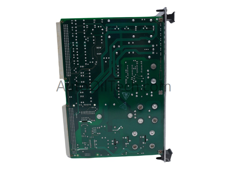
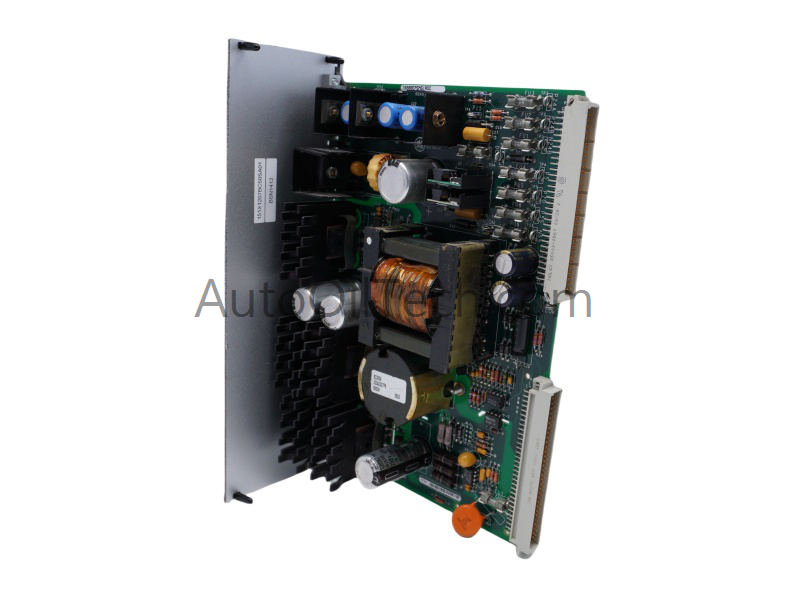
The GE IS200EPSMG1AED Exciter Power Supply Module operates as a dedicated hardware component for converting unregulated input voltage into isolated, multi-rail DC output voltages within EX2100 Excitation Control System platforms.
Hardware Specifications
|
Parameter |
Specification |
|
Model |
IS200EPSMG1AED |
|
Brand |
General Electric (GE) |
|
Series |
EX2100 |
|
Product Type |
Exciter Power Supply Module / Emergency Trip Terminal Board |
|
Origin |
United States |
|
Dimensions |
17.8 cm wide x 33.02 cm high |
|
Operating Temp |
0 to 60 deg C |
|
Technology |
Surface Mount Technology (SMT) |
|
Topology |
Buck Regulator and Push-Pull Inverter |
|
Intermediate Voltage |
50 VDC |
|
Number of Trip Solenoids |
3 |
|
Trip Solenoid Rating |
125 VDC |
|
Analog Voltage Inputs |
6 |
|
Common Mode Voltage Range |
-5 VDC to +5 VDC |
|
Documentation Reference |
GEI-100462A |
Frequently Asked Questions
Q: What differentiates the EPSMG1 from the EPSMG2 variant in application?
A: The EPSMG1 variant (such as the IS200EPSMG1AED) is engineered specifically for the primary excitation control system. It does not contain the Exciter Regulator Power Supply Daughter board (EPSD) that is physically mounted to the EPSMG2 variant used for regulator control.
Q: How does the module achieve electrical isolation between the high-voltage input and the control outputs?
A: Isolation is executed via a high-voltage isolation transformer integrated within the push-pull inverter stage. This physical separation prevents input voltage spikes and transients from damaging the downstream control electronics.
Q: What is the exact operational sequence of the internal voltage regulation circuits?
A: The incoming primary voltage enters a buck regulator stage that drops and stabilizes the electrical potential to a 50 VDC intermediate rail. This 50 VDC rail drives a push-pull inverter, which utilizes the isolation transformer to generate the multiple individual DC output rails required by the system.
Field Installation Guidelines
-
Electrostatic Discharge (ESD) Protection: The printed circuit board utilizes surface mount technology. Personnel must wear a properly grounded ESD wrist strap during handling and insertion phases to prevent latent gate oxide breakdown on solid-state components.
-
Chassis Grounding: Ensure the module is firmly seated into the chassis slot with all retention screws torqued to spec. This establishes a low-impedance path to ground for the internal shield layers, minimizing electromagnetic interference (EMI) on the 6 analog voltage inputs.
-
Terminal and Solenoid Wiring: Terminal connections for the 3 trip solenoids must use wire rated for the 125 VDC nominal solenoid capacity. Ensure common mode voltages on signal inputs do not exceed the +/-5 VDC continuous physical limit relative to signal ground.
-
Convection Clearances: Maintain unobstructed airflow paths above and below the module rack to ensure proper heat sink dissipation profile operations within the 0 to 60 deg C ambient boundary limits.
Have a Question?