- Home
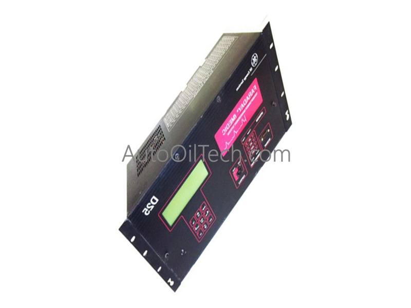
- GE Fanuc D25 Transformer Management System


Sale
GE Fanuc D25 Transformer Management System
No reviews
In stock!
- Part Number: D25
- Brand: GE Fanuc
- Type: Transformer Management System
- Dimensions: 2.1x18.6x26.3cm
- Country of Origin: USA
- Barcode: 8537101190
Share
Product Description
The GE Fanuc D25, also cataloged as the D25 Controller, operates as a dedicated hardware component for automated transformer management and substation control within electrical utility and industrial power distribution networks. The hardware platform executes real-time data acquisition, parameter monitoring, and logical control sequences to monitor power transformer status and coordinate protective automation schemes.
Hardware Specifications
| Parameter | Specification |
|---|---|
| Model | D25 |
| Brand | GE Fanuc (General Electric) |
| Series | D25 Substation Controller / Transformer Management Series |
| Origin | United States / Canada |
| Weight | 15.00 lbs (6.80 kg) |
| Dimensions | Standard rack or panel mount horizontal footprint configuration |
| Operating Temp | Standard electrical substation environmental limits |
| Input Voltage | 120 VAC/DC nominal nominal supply window |
| Line Frequency | 50/60 Hz frequency tolerance |
| Power Consumption | 55 VA maximum maximum electrical intake limit |
| Product Category | Controls & Indicators / Control |
| Control Target | Power transformers and intelligent electronic device (IED) loops |
Backplane Bus Communication Velocity and Processing
The controller utilizes internal high-density processing components to optimize communication velocity and routing speeds across the backplane bus structure. Maintaining strict firmware flash compatibility standards across all internal modules ensures synchronous polling of physical analog inputs and discrete digital contacts. The processing core resolves complex automation logic within deterministic calculation windows, allowing calculated alarm bits and monitoring parameters to distribute over the internal bus architecture and report to remote DCS or SCADA networks without data buffering or latency bottlenecks.
Frequently Asked Questions
Q: What are the electrical connection tolerances for the primary auxiliary power module of the D25?
A: The D25 power infrastructure accepts a universal nominal input voltage of 120 VAC/DC, allowing operation from either alternating current lines or station battery direct current banks. Under peak data processing and full I/O configuration load, the system power consumption is limited to a maximum threshold of 55 VA.
Q: How can technicians maintain structural data consistency during a controller firmware replacement or flash routine?
A: Before executing a firmware flash modification, technicians must verify the absolute compatibility of the application software with the target hardware revision level. System configuration data must be backed up via the serial diagnostic interface to prevent total register erasure or memory structure corruption during the active non-volatile memory write cycle.
Have a Question?