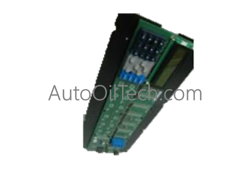
Configured for high-speed data transfer and internal bus communication in GE Universal Relay (UR) Series networks, the GE Fanuc 12A0-0102-A1 (12A0-0102-A1 UR Series Bus Board) provides direct physical/electrical execution.
Suffix Breakdown & Model Matrix
Model Suffix
Core Function Architecture
Architectural Application
12A0-0102-A1
Standard Internal Backplane Bus Board
GE Universal Relay (UR) Series
12A0-0102-...
Base Variant Family
Multilin Protective Relay Frameworks
Hardware Specifications
Parameter
Specification
Model
12A0-0102-A1
Brand
GE Fanuc
Origin
USA
Weight
0.65 kg
Dimensions
250.0 mm x 120.0 mm x 20.0 mm
Operating Temp
-40 deg C to +70 deg C
Power Consumption
5.0 W nominal
Operating Voltage
24 VDC
Communication Interface
Internal high-speed backplane bus
System Compatibility
GE UR Series, UR200 models
Profinet / EtherNet/IP Deterministic Networks and Firmware Flash Compatibility
The 12A0-0102-A1 bus board utilizes robust backplane bus communication velocity architecture to manage data exchange rates across modular UR relay subsystems. It maintains low-latency signal distribution between plug-in processing modules and power units while withstanding severe industrial electromagnetic interference. Furthermore, internal firmware flash compatibility ensures that onboard bus controller logic can be updated via authorized management tools without requiring hardware replacement.
Frequently Asked Questions
Q: What is the primary function of the 12A0-0102-A1 board within the UR relay architecture?
A: It serves as the internal backplane bus board, providing high-speed data communication and power distribution links between the various plug-in modules of the GE Universal Relay system.
Q: What nominal voltage does the bus board require for internal system operation?
A: The board operates on a regulated DC power input of 24 VDC supplied by the main power supply module of the relay chassis.
Field Installation Guidelines
Ensure that all external AC and DC power sources to the UR relay chassis are completely disconnected before installing or replacing the 12A0-0102-A1 bus board. Handle the printed circuit board by its edges while wearing an ESD wrist strap to prevent electrostatic discharge damage to sensitive components. Slide the board securely into its designated backplane mounting slots, ensuring all edge connectors are fully seated before fastening securing screws.