- Home
- GE F650MFBF2G0HI Distribution Relays


Sale
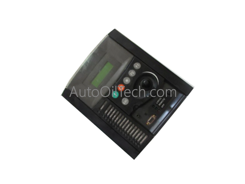
GE F650MFBF2G0HI Distribution Relays
No reviews
In stock!
- Part Number: F650MFBF2G0HI
- Brand: General Electric
- Type: Distribution Relays
- Dimensions: 33x17.7x5.5cm
- Country of Origin: USA
- Barcode: 8537101190
Share
Additional Specifications
| Color / Pattern |
|
| Power Source |
|
| Communication Protocols |
|
| Controller Design |
|
Product Description
The GE Multilin F650MFBF2G0HI, also cataloged as the F650 Digital Bay Controller, operates as a dedicated hardware component for multi-phase electrical parameter evaluation, high-speed protection coordination, and distribution bus automation within power substations. Configured with a large LCD display and 6 independent setting groups, the solid-state protection node provides direct physical/electrical execution to monitor feeder networks and drive breaker actuation matrices across ring-bus, double breaker, and breaker-and-a-half topologies.
Hardware Specifications
| Parameter | Specification |
|---|---|
| Model | F650MFBF2G0HI |
| Brand | GE (General Electric Multilin) |
| Origin | USA |
| Weight | Standard F650 series 19-inch rack-mount mass profile |
| Mounting Profile | Standard 19-inch rack mountable configuration |
| Operating Temp | -40 to +85 deg C continuous substation limits |
| Power Consumption | Standard universal voltage options matching the F650 series rails |
| Display Interface | Large LCD display unit for status, alarm, and parameter tracking |
| Protection Schemes | 6 independent programmable setting groups |
| Automation Logic | Integrated load shedding, transfer schemes, and automated fault execution |
| I/O Configuration | Programmable digital inputs and outputs |
| Functional Profile | Feeder protection against overcurrent, short circuits, and earth faults |
| Product Type | Transmission and Distribution Relays |
Industrial Control & Distributed System Infrastructure
- Backplane Bus Communication Velocity and Processing Constraints The internal processing tier handles real-time analog signal acquisition, short-circuit calculations, and instantaneous overcurrent trips within a deterministic microsecond logic loop. This high-velocity execution design allows the main microprocessor to evaluate multiple protection scheme branches concurrently across 6 setting groups without inducing backplane data processing lag.
- Profinet / EtherNet/IP Deterministic Networks and SCADA Scaling The communication interface layout incorporates multiple dedicated network ports to manage concurrent data streams to supervisory SCADA layers. This high-velocity throughput supports real-time I/O status scaling and complex automated transfer schemes across distributed substation hardware nodes, minimizing data packet serialization latency during heavy line fault surges.
Frequently Asked Questions
Q: How do the 6 independent setting groups function within the feeder protection architecture?
A: The 6 setting groups act as completely separate configuration profiles stored natively in the relay's non-volatile memory. Technicians can pre-program distinct overcurrent thresholds, time-delay curves, and automation logic blocks for different network running conditions (such as peak load vs. low-load generation or grid reconfigurations), switching between profiles via a digital input or network command with zero logic processing delay.
Q: What protection behavior occurs if ambient temperatures in the substation enclosure reach the +85 deg C boundary?
A: The solid-state internal components are structurally rated to sustain continuous operation up to +85 deg C without thermal drift or degradation of the analog-to-digital measurement accuracy. If localized thermal boundaries are breached, internal diagnostic self-tests will flag a thermal warning code on the SCADA bus, while the core protection logic maintains active tracking to prevent uncommanded system resets.
Have a Question?