- Home
- GE F650GNFBF1G0HICE Multilin F650 Series Digital Bay Controller


Sale
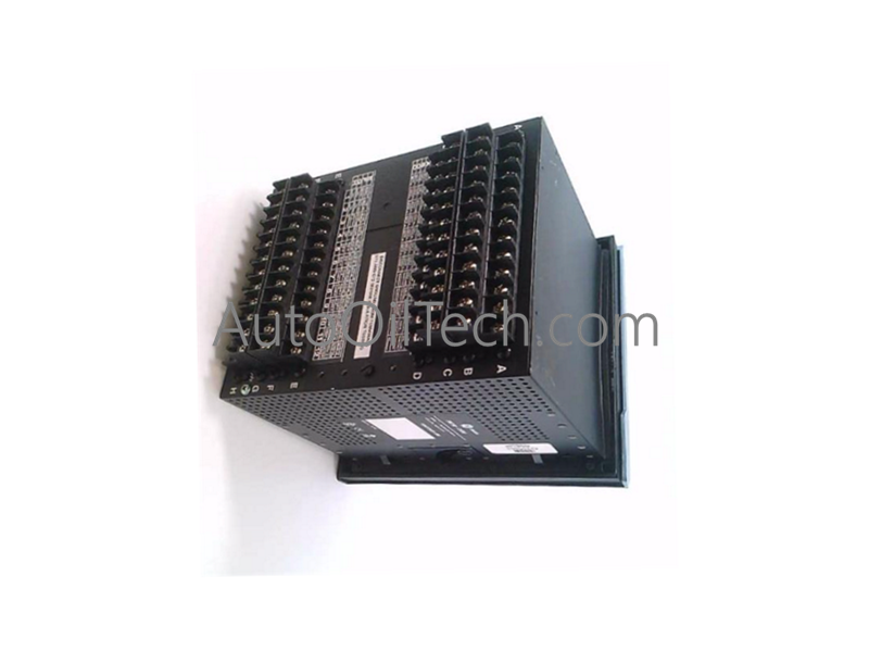
GE F650GNFBF1G0HICE Multilin F650 Series Digital Bay Controller
No reviews
In stock!
- Part Number: F650GNFBF1G0HICE
- Brand: General Electric
- Type: Digital Bay Controller
- Dimensions: 33x17.7x5.5cm
- Country of Origin: USA
- Barcode: 8537101190
Share
Additional Specifications
| Color / Pattern |
|
| Power Source |
|
| Communication Protocols |
|
| Controller Design |
|
Product Description
The GE F650GNFBF1G0HICE serves as the primary F650 Digital Bay Controller utilized to execute multi-phase parameter evaluation, protective fault isolation, and breaker control actuation across substation automation platforms. Configured with a dedicated local HMI and high-density logic arrays, the solid-state protection node provides direct physical/electrical execution to manage breaker lines and load shedding matrices over industrial power networks.
Hardware Specifications
| Parameter | Specification |
|---|---|
| Model | F650GNFBF1G0HICE |
| Brand | GE (General Electric Multilin) |
| Origin | USA |
| Weight | Standard F650 series 19-inch rack-mount mass profile |
| Dimensions | Standard F650 series panel-mount chassis envelope |
| Operating Temp | -40 to +70 deg C continuous operational limits |
| Power Supply Options | 110-240 V AC or 24-125 V DC operational input rails |
| Relative Humidity | 10% to 95% RH, non-condensing operational envelope |
| Core Protection Functions | Overcurrent | Directional overcurrent | Breaker failure protection |
| System Management | Voltage and frequency monitoring | Load shedding and restoration |
| Protocol Suite | IEC 61850, Modbus, and DNP3 native communication profiles |
| Control Matrix | Configurable relay outputs for automated actuation schemes |
| Diagnostic Capabilities | Waveform event recording and advanced fault analysis logging |
| Display Interface | Integrated LCD screen human-machine interface (HMI) |
| Compliance Standards | IEC 60068 shock and vibration resistance compliant |
| Product Type | Transmission and Distribution Relays |
Industrial Control & Distributed System Infrastructure
- Backplane Bus Communication Velocity and Protection Overheads The controller utilizes high-speed internal arithmetic processors to handle multi-phase fault detection and directional tracking within fixed microsecond execution windows. The core protection engine runs concurrent checking cycles natively at the hardware tier, ensuring that critical breaker failure commands pass from detection blocks to active output relay drivers without backplane bus serialization delay.
- Profinet / EtherNet/IP Deterministic Networks and Multi-Protocol Scaling The communication interface layer supports simultaneous data routing across modern IEC 61850, Modbus, and DNP3 architectures to streamline substation automation. This high-bandwidth throughput manages real-time I/O status scaling, enabling automated load shedding matrices and fault analysis logs to broadcast across network boundaries while minimizing data packet serialization latency under heavy traffic conditions.
Frequently Asked Questions
Q: How does the integrated breaker failure protection function execute within the control loop?
A: When a primary protection element (such as directional overcurrent) initiates a trip command to the local circuit breaker, the breaker failure logic starts an internal high-resolution hardware timer while monitoring the phase current lines. If the breaker fails to clear the fault and current continues to flow past the pre-set timing threshold, the relay automatically fires its auxiliary outputs to trip adjacent upstream breakers and isolate the faulted bus section.
Q: What structural protection measures exist to stabilize the relay logic if input control voltages fluctuate?
A: The module's internal power supply is engineered with robust buck-boost regulation stages to isolate internal CMOS logic rails from severe auxiliary line disturbances. Whether operating on the 110-240 V AC or the 24-125 V DC input rail, the power stage absorbs transient drops and inductive switching surges, keeping the internal analog-to-digital converters and processing cores running without triggering uncommanded system resets.
Have a Question?