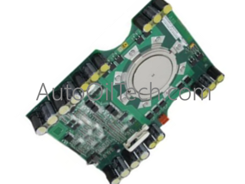
The ABB 5SHX10H6004, also cataloged as the 5SHX10H6004 IGCT Module, operates as a dedicated hardware component for high-power semiconductor switching within power electronics and industrial drive platforms.
Hardware Specifications
Parameter
Specification
Model
5SHX10H6004
Brand
ABB
Origin
Switzerland
Product Type
IGCT Modules
Repetitive Peak Off-State Voltage
3300 V
Turn-On Delay (tdon)
Less than 3 us
Turn-Off Delay (tdoff)
Less than 6 us
Precise Timing Turn-Off Variant
Less than 800 ns
Signal Input Types
Analog (-10 V to +10 V, 4-20 mA), Digital (TTL/CMOS)
Signal Processing Precision
Greater than or equal to 16-bit ADC for analog, nanosecond-level for digital
Mounting Force
40 kN
Weight
2.9 kg
Dimensions
Standard press-pack housing dimensions for 3300 V IGCT
Operating Temp
-40 to 125 deg C junction temperature range
Power Consumption
Internal gate unit losses dependent on switching frequency
Firmware Flash Compatibility and Drive Integration
The device utilizes localized gate driver electronics coupled via direct fiber optic control interfaces to achieve high galvanic isolation and rapid signal transmission. The module architecture ensures firmware flash compatibility with broader ABB ACS platform application layers, coordinating gate pulse delivery to match specified backplane bus communication velocity guidelines. This integration permits the host processing system to manage synchronized multi-unit switching sequences without execution latency. Real-time monitoring structures track inner circuit parameters, enabling automated protection deployment during overcurrent states across high I/O density scaling frameworks.
Frequently Asked Questions
Q: What type of interface is required to control the gate unit on this module?
A: The module utilizes a direct integrated optical interface. Control signals must be transmitted via fiber optic cables to the gate drive board to ensure electrical isolation and high electromagnetic immunity.
Q: What is the purpose of the specified 40 kN mounting force?
A: The 40 kN clamping force is mandatory to achieve optimal thermal and electrical contact resistance across the internal free-floating silicon layers. Deviation from this mechanical load specification will result in hardware degradation or thermal runaway under load conditions.